|
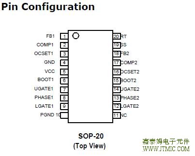
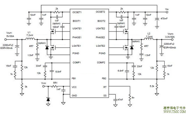
CXSD62117双通道电压模式和同步PWM控制器驱动双N通道mosfet两个通道均采用180度相移 | |||||||||||||||||||||||||||||||||||||||||||||||||||||||||||||||||||||||||||||||||||||||||||||||||||||||||||||||||||||||||||||||||||||||||||||||||||||||||||||||||||||||||||||||||||||||||||||||||||||||||||||||||||||||||||||||||||||||||||||||||||||||||||||
|
Layout Consideration indicating high current paths; these traces must be short and wide. Components along the bold lines should be placed lose together. Below is a checklist for your layout:- Keep the switching nodes (UGATE, LGATE, and PHASE)away from sensitive small signal nodes since these nodes are fast moving signals. Therefore, keep traces - Place the source of the high-side MOSFET and the drainof the low-side MOSFET as close as possible. Minimiz-ing the impedance with wide layout plane between the two pads reduces the voltage bounce of the node. - Decoupling capacitor, compensation component, the resistor dividers, and boot capacitors should be close their pins. (For example, place the decoupling ceramic capacitor near the drain of the high-side MOSFET as 八,相关产品 更多同类产品......
发表评论
| |||||||||||||||||||||||||||||||||||||||||||||||||||||||||||||||||||||||||||||||||||||||||||||||||||||||||||||||||||||||||||||||||||||||||||||||||||||||||||||||||||||||||||||||||||||||||||||||||||||||||||||||||||||||||||||||||||||||||||||||||||||||||||||
发表时间:2020-04-24浏览次数:172
| 最新信息 |
|---|
| (1.)CXDC6584HV 100V集成M ... (2.)CXSD1018AH 100V低内 ... (3.)CXDC6574HV 120V降压 ... (4.)CXPR7166 单节锂离子/ ... (5.)CXMD32126 双通道H桥 ... (6.)CXMD32108R/S:高性能无 ... (7.)CXLE86143 高功率因数 ... (8.)CXLE8278 高效升压型L ... (9.)CXSU63180 10A非同步 ... (10.)CXLB73269太阳能供电 ... |
| 头条信息 |
|---|


