|
5A同步降压转换器CXSD62122 50mΩ P沟道功率MOSFET和20mΩ N沟道功率MOSFET电流模式控制方案 | ||||||||||||||||||||||||||||||||||||||||||||||||||||||||||||||||||||||||||||||||||||||||||||||||||||||||||||||||||||||||||||||||||||||||||||||||||||||||||||||||||||||||||||||||||||||||||||||||||||||||||||||||||||||||||||||||||||||||||||||||||||||||||||||||
|
目录 1.产品概述 2.产品特点 一,产品概述(General Description) The CXSD62122 is a 5A, synchronous, step-down converter with integrated 50mΩ P-channel power MOSFET and 20mΩ N-channel power MOSFET.The device, with cur-rent-mode control scheme, can convert 4.5~26V input volt-age to the output voltage adjustable from 0.8 to 90% VIN to provide excellent output voltage regulation. Wide Input Voltage from 4.5V to 26V LCD Monitor / TV SetTop Box 四.下载产品资料PDF文档 需要详细的PDF规格书请扫一扫微信联系我们,还可以获得免费样品以及技术支持! 五,产品封装图 (Package)
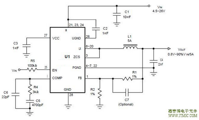
六.电路原理图
七,功能概述 Inductor Value Calculation the use of a smaller inductor for the same amount of inductor ripple current. However, this is at the expense of efficiency due to an increase in MOSFET gate charge losses. The equation (2) shows that the inductance value has a direct effect on ripple current.Accepting larger values of ripple current allows the use of low inductances, but results in higher output voltage ripple In general, interconnecting impedance should be minimized by using short, wide printed circuit traces. Signal and power grounds are to be kept separating and finally com-bined using ground plane construction or single point grounding. Figure 2 illustrates the layout, with bold lines indicating high current paths. Components along the bold lines should be placed close together. The following is a checklist for your layout:
发表评论
| ||||||||||||||||||||||||||||||||||||||||||||||||||||||||||||||||||||||||||||||||||||||||||||||||||||||||||||||||||||||||||||||||||||||||||||||||||||||||||||||||||||||||||||||||||||||||||||||||||||||||||||||||||||||||||||||||||||||||||||||||||||||||||||||||
发表时间:2020-04-24浏览次数:162
| 最新信息 |
|---|
| (1.)CXDC6584HV 100V集成M ... (2.)CXSD1018AH 100V低内 ... (3.)CXDC6574HV 120V降压 ... (4.)CXPR7166 单节锂离子/ ... (5.)CXMD32126 双通道H桥 ... (6.)CXMD32108R/S:高性能无 ... (7.)CXLE86143 高功率因数 ... (8.)CXLE8278 高效升压型L ... (9.)CXSU63180 10A非同步 ... (10.)CXLB73269太阳能供电 ... |
| 头条信息 |
|---|


