|
两个低电压降调节器CXSD62114双降压恒定时间同步PWM控制器内部转换MOSFET | ||||||||||||||||||||||||||||||||||||||||||||||||||||||||||||||||||||||||||||||||||||||||||||||||||||||||||||||||||||||||||||||||||||||||||||||||||||||||||||||||||||||||||||||||||||||||||||||||||||||||||||||||||||||||||||||||||||||||||||||||||||||
|
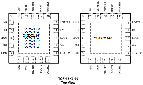
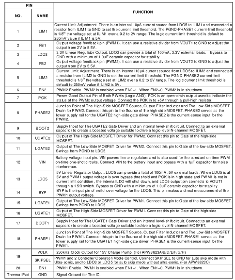
目录 1.产品概述 2.产品特点 一,产品概述(General Description) The CXSD62114 integrates dual step-down, constant-on-time, synchronous PWM controllers (that drives dual N-channel MOSFETs for with loading-modulated switching frequencies. The Forced-PWM Mode works nearly at constant frequency for low-noise requirements. The unique ultrasonic Wide Input voltage Range from 5.5V to 25V Notebook and Sub-Notebook Computers 需要详细的PDF规格书请扫一扫微信联系我们,还可以获得免费样品以及技术支持! 五,产品封装图 (Package)
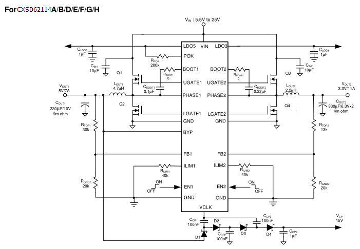
六.电路原理图
七,功能概述 the node. Decoupling capacitor, the resistor dividers, boot capacitors, and current-limit stetting resistor should be close to their pins. (For example, place the decoupling ceramic capacitor near the drain of the high-side MOSFET as close as possible. The bulk capacitors are also placednear the drain). The input capacitor should be near the drain of the upper MOSFET; the high quality ceramic decoupling capacitor can be put close to the VCC and GND pins;the output capacitor should be near the loads. The input capacitor GND should be close to the output ca-pacitor GND and the lower MOSFET GND. The drain of the MOSFETs (V IN and PHASEx nodes)should be a large plane for heat sinking. And PHASEx pin traces are also the return path for UGATEx. Con-nect these pins to the respective converter’s upper MOSFET source. The controller used ripple mode control. Build the re-sistor divider close to the FB1 pin so that the high impedance trace is shorter when the output voltage is in ad justable mode. And the FB1 pin traces can’t be close to the switching signal traces (UGATEx, LGATEx,BOOTx, and PHASEx). The PGND trace should be a separate trace, and in-dependently go to the source of the low-side MOSFETs for current-limit accuracy. 八,相关产品 更多同类产品......
发表评论
| ||||||||||||||||||||||||||||||||||||||||||||||||||||||||||||||||||||||||||||||||||||||||||||||||||||||||||||||||||||||||||||||||||||||||||||||||||||||||||||||||||||||||||||||||||||||||||||||||||||||||||||||||||||||||||||||||||||||||||||||||||||||
发表时间:2020-04-23浏览次数:162
| 最新信息 |
|---|
| (1.)CXDC6584HV 100V集成M ... (2.)CXSD1018AH 100V低内 ... (3.)CXDC6574HV 120V降压 ... (4.)CXPR7166 单节锂离子/ ... (5.)CXMD32126 双通道H桥 ... (6.)CXMD32108R/S:高性能无 ... (7.)CXLE86143 高功率因数 ... (8.)CXLE8278 高效升压型L ... (9.)CXSU63180 10A非同步 ... (10.)CXLB73269太阳能供电 ... |
| 头条信息 |
|---|


